5.5. Tensors
A tensor is a multi-dimensional matrix structure in the memory. Tensor is defined by the following properties:
- Dimensionality
- Dimension sizes across each dimension
- Individual element types
- Tensor stride across each dimension
PTX supports instructions which can operate on the tensor data. PTX Tensor instructions include:
- Copying data between global and shared memories
- Reducing the destination tensor data with the source.
The Tensor data can be operated on by various wmma.mma, mma and wgmma.mma_async instructions.
PTX Tensor instructions treat the tensor data in the global memory as a multi-dimensional structure and treat the data in the shared memory as a linear data.
5.5.1. Tensor Dimension, size and format
Tensors can have dimensions: 1D, 2D, 3D, 4D or 5D.
Each dimension has a size which represents the number of elements along the dimension. The elements can have one the following types:
- Bit-sized type:
.b32,.b64 - Sub-byte types:
.b4x16,.b4x16_p64,.b6x16_p32,.b6p2x16 - Integer:
.u8,.u16,.u32,.s32,.u64,.s64 - Floating point and alternate floating point:
.f16,.bf16,.tf32,.f32,.f64(rounded to nearest even).
Tensor can have padding at the end in each of the dimensions to provide alignment for the data in the subsequent dimensions. Tensor stride can be used to specify the amount of padding in each dimension.
5.5.1.1. Sub-byte Types
5.5.1.1.1. Padding and alignment of the sub-byte types
The sub-byte types are expected to be packed contiguously in the global memory and the Tensor copy instruction will expand them by appending empty spaces as shown below:
Type .b4x16: With this type, there is no padding involved and the packed sixteen .b4 elements in a 64-bits container is copied as is between the shared memory and the global memory.
Type .b4x16_p64: With this type, sixteen contiguous 4-bits of data is copied from global memory to the shared memory with the append of 64-bits of padding as shown in Figure 5.
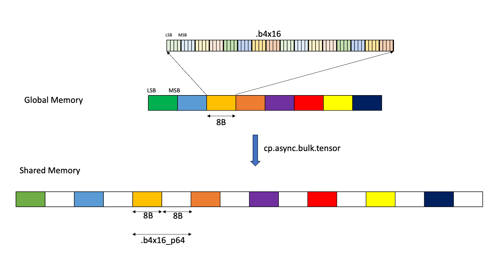
Figure 5 Layout for .b4x16_p64
The padded region that gets added is un-initialized.
Type .b6x16_p32: With this type, sixteen 6-bits of data is copied from global memory to the shared memory with an append of 32-bits of padding as shown in Figure 6.
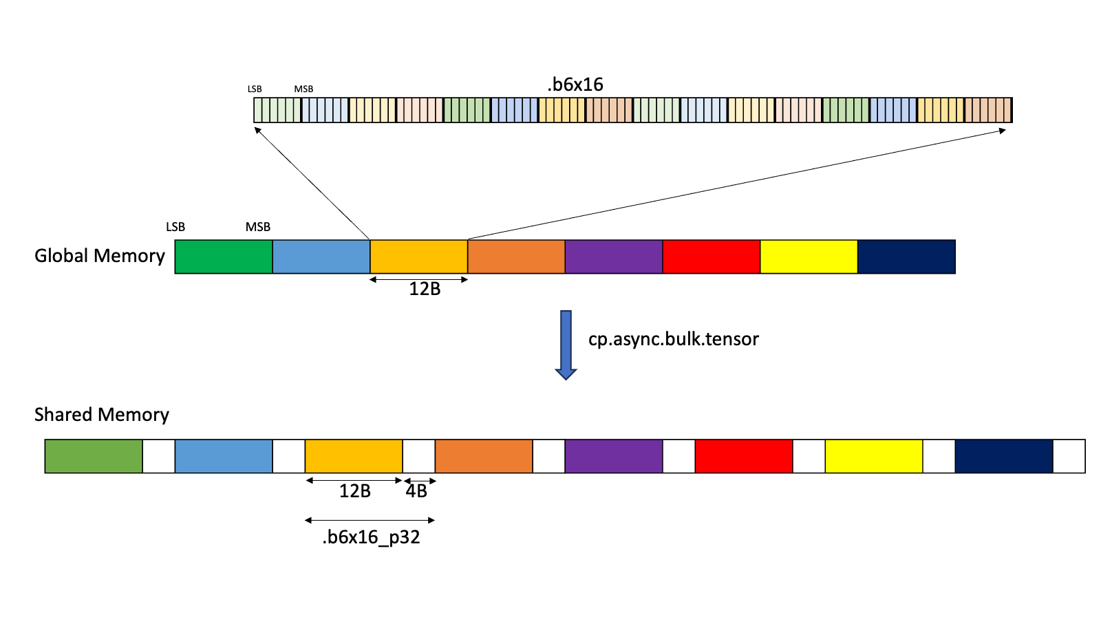
Figure 6 Layout for .b6x16_p32
The padded region that gets added is un-initialized.
Type .b6p2x16: With this type, sixteen elements, each containing 6-bits of data at the LSB and 2-bits of padding at the MSB, are copied from shared memory into the global memory by discarding the 2-bits of padding data and packing the 6-bits data contiguously as shown in Figure 7.
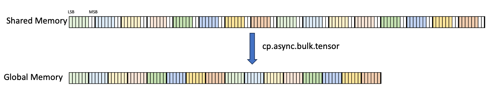
Figure 7 Layout for .b6p2x16
In case of .b6x16_p32 and .b4x16_p64, the padded region that gets added is un-initialized.
The types .b6x16_p32 and .b6p2x16 share the same encoding value in the descriptor (value 15) as the two types are applicable for different types of tensor copy operations:
| Type | Valid Tensor Copy Direction |
|---|---|
.b6x16_p32 |
.shared::cluster.global, .shared::cta.global |
.b6p2x16 |
.global.shared::cta |
5.5.2. Tensor Access Modes
Tensor data can be accessed in two modes:
Tiled mode:
In tiled mode, the source multi-dimensional tensor layout is preserved at the destination.
Im2col mode:
In im2col mode, the elements in the Bounding Box of the source tensor are rearranged into columns at the destination. Refer here for more details.
5.5.3. Tiled Mode
This section talks about how Tensor and Tensor access work in tiled mode.
5.5.3.1. Bounding Box
A tensor can be accessed in chunks known as Bounding Box. The Bounding Box has the same dimensionality as the tensor they are accessing into. Size of each bounding Box must be a multiple of 16 bytes. The address of the bounding Box must also be aligned to 16 bytes.
Bounding Box has the following access properties:
- Bounding Box dimension sizes
- Out of boundary access mode
- Traversal strides
The tensor-coordinates, specified in the PTX tensor instructions, specify the starting offset of the bounding box. Starting offset of the bounding box along with the rest of the bounding box information together are used to determine the elements which are to be accessed.
5.5.3.2. Traversal-Stride
While the Bounding Box is iterating the tensor across a dimension, the traversal stride specifies the exact number of elements to be skipped. If no jump over is required, default value of 1 must be specified.
The traversal stride in dimension 0 can be used for the Interleave layout. For non-interleaved layout, the traversal stride in dimension 0 must always be 1.
Figure 8 illustrates tensor, tensor size, tensor stride, Bounding Box size and traversal stride.
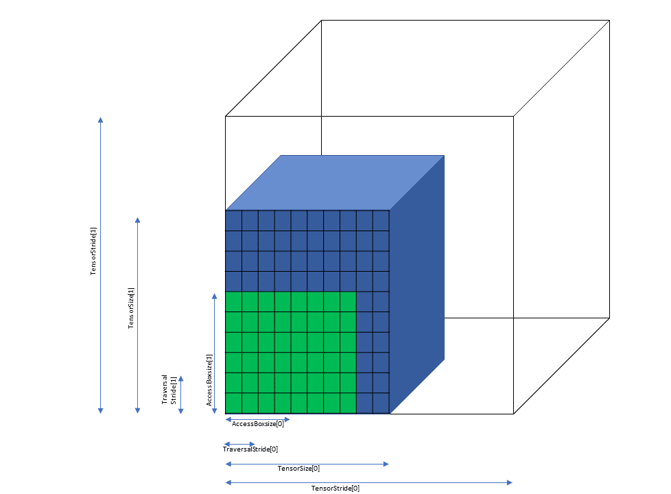
Figure 8 Tiled mode bounding box, tensor size and traversal stride
5.5.3.3. Out of Boundary Access
PTX Tensor operation can detect and handle the case when the Bounding Box crosses the tensor boundary in any dimension. There are 2 modes:
Zero fill mode:
Elements in the Bounding Box which fall outside of the tensor boundary are set to 0.
OOB-NaN fill mode:
Elements in the Bounding Box which fall outside of the tensor boundary are set to a special NaN called OOB-NaN.
Figure 9 shows an example of the out of boundary access.
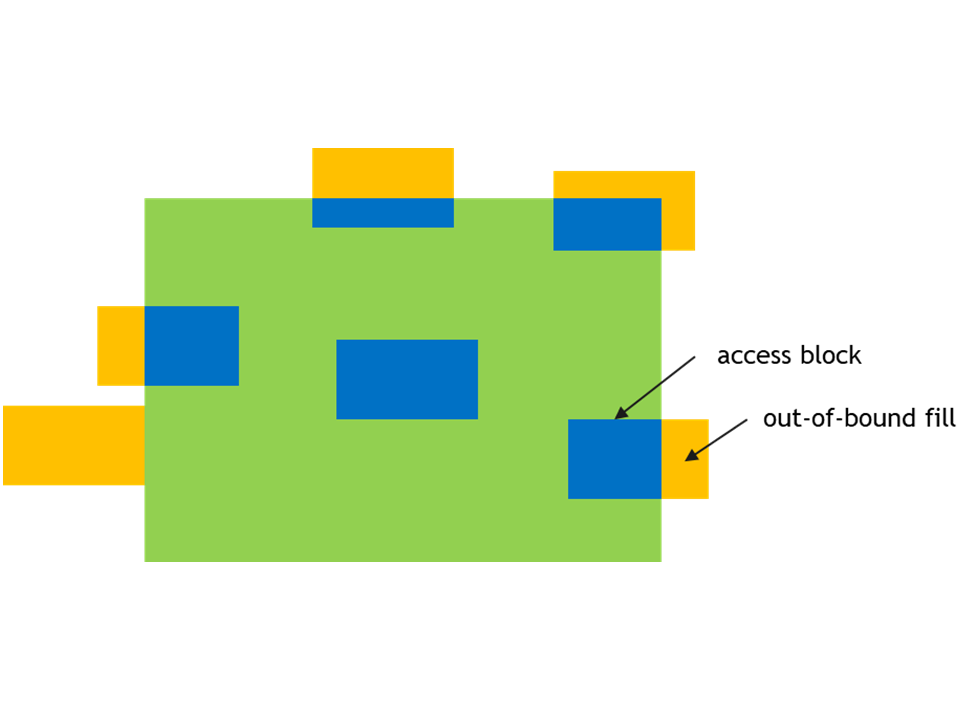
Figure 9 Out of boundary access
5.5.3.4. .tile::scatter4 and .tile::gather4 modes
These modes are similar to the tiled mode with restriction that these modes work only on 2D tensor data. Tile::scatter4 and Tile::gather4 modes are used to access multiple non-contiguous rows of tensor data.
In Tile::scatter4 mode single 2D source tensor is divided into four rows in the 2D destination tensor. In Tile::gather4 mode four rows in the source 2D tensor are combined to form single 2D destination tensor.
These modes work on four rows and hence the instruction will take:
- four tensor coordinates across the dimension 0
- one tensor coordinate across the dimension 1
The interleave layout is not supported for .tile::scatter4 and .tile::gather4 modes.
All other constraints and rules of the tile mode apply to these modes as well.
5.5.3.4.1. Bounding Box
For Tile::scatter4 and Tile::gather4 modes, four request coordinates will form four Bounding Boxes in the tensor space.
Figure 10 shows an example of the same with start coordinates (1, 2), (1, 5), (1, 0) and (1, 9).
The size of the bounding box in the dimension 0 represents the length of the rows. The size of the bounding box in the dimension 1 must be one.
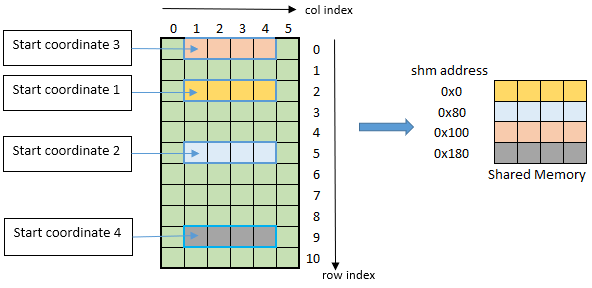
Figure 10 tiled::scatter4/tiled::gather4 mode bounding box example
5.5.4. im2col mode
Im2col mode supports the following tensor dimensions: 3D, 4D and 5D. In this mode, the tensor data is treated as a batch of images with the following properties:
- N: number of images in the batch
- D, H, W: size of a 3D image (depth, height and width)
- C: channels per image element
The above properties are associated with 3D, 4D and 5D tensors as follows:
| Dimension | N/D/H/W/C applicability |
|---|---|
| 3D | NWC |
| 4D | NHWC |
| 5D | NDHWC |
5.5.4.1. Bounding Box
In im2col mode, the Bounding Box is defined in DHW space. Boundaries along other dimensions are specified by Pixels-per-Column and Channels-per-Pixel parameters as described below.
The dimensionality of the Bounding Box is two less than the tensor dimensionality.
The following properties describe how to access the elements in im2col mode:
- Bounding-Box Lower-Corner
- Bounding-Box Upper-Corner
- Pixels-per-Column
- Channels-per-Pixel
Bounding-box Lower-Corner and Bounding-box Upper-Corner specify the two opposite corners of the Bounding Box in the DHW space. Bounding-box Lower-Corner specifies the corner with the smallest coordinate and Bounding-box Upper-Corner specifies the corner with the largest coordinate.
Bounding-box Upper- and Lower-Corners are 16-bit signed values whose limits varies across the dimensions and are as shown below:
| 3D | 4D | 5D | |
|---|---|---|---|
| Upper- / Lower- Corner sizes | [-2¹⁵, 2¹⁵-1] | [-2⁷, 2⁷-1] | [-2⁴, 2⁴-1] |
Figure 11 and Figure 12 show the Upper-Corners and Lower-Corners.
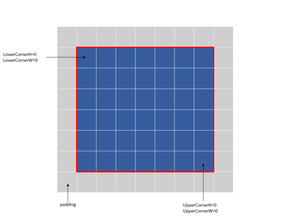
Figure 11 im2col mode bounding box example 1
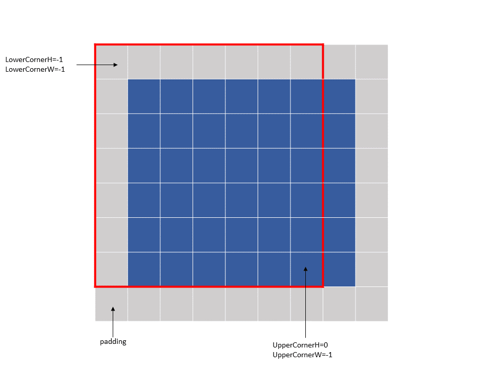
Figure 12 im2col mode bounding box example 2
The Bounding-box Upper- and Lower- Corners specify only the boundaries and not the number of elements to be accessed. Pixels-per-Column specifies the number of elements to be accessed in the NDHW space.
Channels-per-Pixel specifies the number of elements to access across the C dimension.
The tensor coordinates, specified in the PTX tensor instructions, behave differently in different dimensions:
- Across N and C dimensions: specify the starting offsets along the dimension, similar to the tiled mode.
- Across DHW dimensions: specify the location of the convolution filter base in the tensor space. The filter corner location must be within the bounding box.
The im2col offsets, specified in the PTX tensor instructions in im2col mode, are added to the filter base coordinates to determine the starting location in the tensor space from where the elements are accessed.
The size of the im2col offsets varies across the dimensions and their valid ranges are as shown below:
| 3D | 4D | 5D | |
|---|---|---|---|
| im2col offsets range | [0, 2¹⁶-1] | [0, 2⁸-1] | [0, 2⁵-1] |
Following are some examples of the im2col mode accesses:
Example 1 (Figure 13):
Tensor Size[0] = 64
Tensor Size[1] = 9
Tensor Size[2] = 14
Tensor Size[3] = 64
Pixels-per-Column = 64
channels-per-pixel = 8
Bounding-Box Lower-Corner W = -1
Bounding-Box Lower-Corner H = -1
Bounding-Box Upper-Corner W = -1
Bounding-Box Upper-Corner H = -1.

tensor coordinates = (7, 7, 4, 0)
im2col offsets : (0, 0)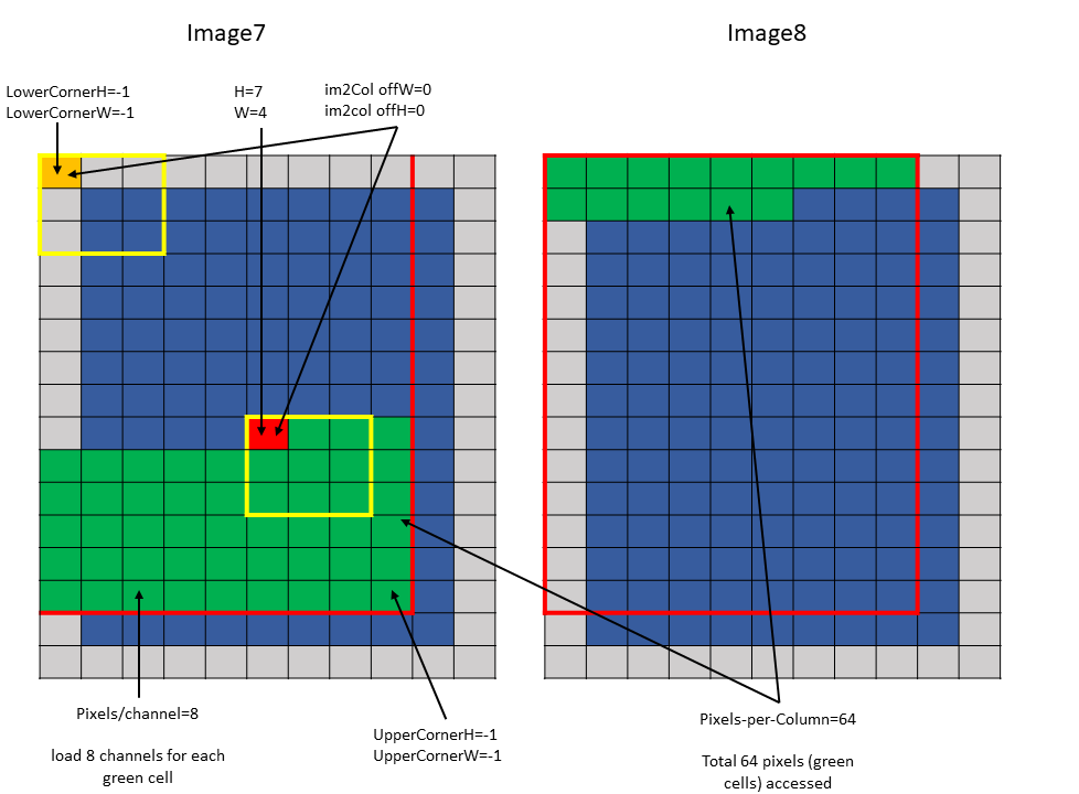
Figure 13 im2col mode example 1
Example 2 (Figure 14):
Tensor Size[0] = 64
Tensor Size[1] = 9
Tensor Size[2] = 14
Tensor Size[3] = 64
Pixels-per-Column = 64
channels-per-pixel = 8
Bounding-Box Lower-Corner W = 0
Bounding-Box Lower-Corner H = 0
Bounding-Box Upper-Corner W = -2
Bounding-Box Upper-Corner H = -2

tensor coordinates = (7, 7, 4, 0)
im2col offsets: (2, 2)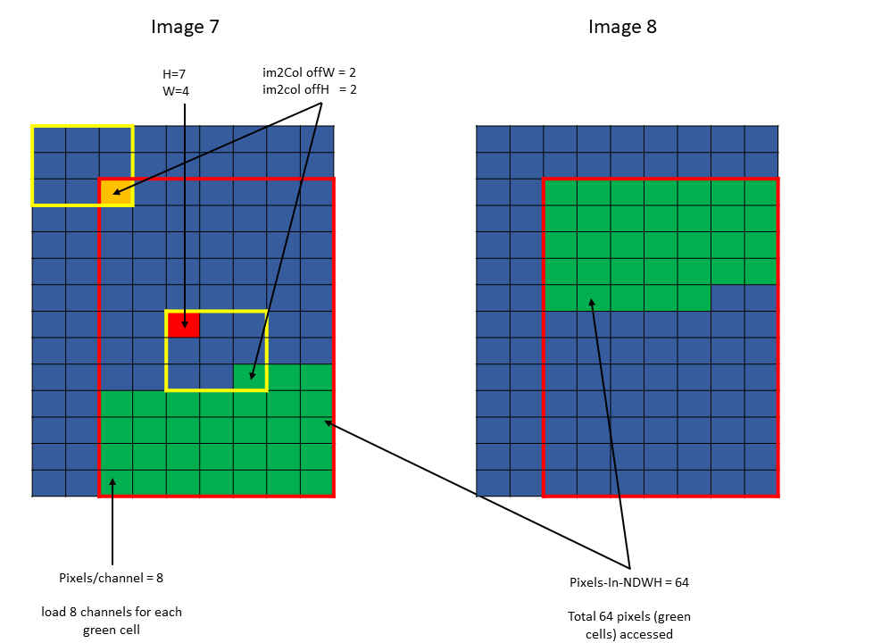
Figure 14 im2col mode example 2
5.5.4.2. Traversal Stride
The traversal stride, in im2col mode, does not impact the total number of elements (or pixels) being accessed unlike the tiled mode. Pixels-per-Column determines the total number of elements being accessed, in im2col mode.
The number of elements traversed along the D, H and W dimensions is strided by the traversal stride for that dimension.
The following example with Figure 15 illustrates access with traversal-strides:
Tensor Size[0] = 64
Tensor Size[1] = 8
Tensor Size[2] = 14
Tensor Size[3] = 64
Traversal Stride = 2
Pixels-per-Column = 32
channels-per-pixel = 16
Bounding-Box Lower-Corner W = -1
Bounding-Box Lower-Corner H = -1
Bounding-Box Upper-Corner W = -1
Bounding-Box Upper-Corner H = -1.
Tensor coordinates in the instruction = (7, 7, 5, 0)
Im2col offsets in the instruction : (1, 1)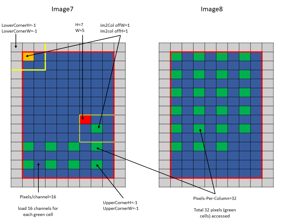
Figure 15 im2col mode traversal stride example
5.5.4.3. Out of Boundary Access
In im2col mode, when the number of requested pixels in NDHW space specified by Pixels-per-Column exceeds the number of available pixels in the image batch then out-of-bounds access is performed.
Similar to tiled mode, zero fill or OOB-NaN fill can be performed based on the Fill-Mode specified.